Research in Our Lab
|
Developing Constitutive Equations for Two-Fluid Models
|
| Particulate flows have a wide range of applications, such as sedimentation process, fluidized bed reactors, and pneumatic conveying. There are two different approaches in modeling particulate flows: Eulerian-Lagrangian approach and Eulerian-Eulerian approach or two-fluid model (TFM). In the Eulerian-Lagrangian approach the particles are tracked individually and their dynamics are solved by the Lagrangian method. In the TFM, the large number of particles (solid phase) are considered to constitute a continuum phase or a virtual fluid; the motion of the solid phase is described by the momentum transport equations similar to the Navier-Stokes equations. Most engineering applications require the use of TFM for better understanding and predicting the performance because of their large scales in terms of the number of particles and the size of devices. However, the primary challenge of two-fluid modeling is the development of constitutive equations for solid phase. For example, it is well known that most real fluids, like air or water, can be considered a Newtonian fluid with a viscosity that is well defined and measurable. However, the determination of viscosity of solid phase remains an open problem; furthermore, the no-slip boundary condition commonly used for viscous fluid may not be applicable to the solid phase.Our approach is to use more detailed Eulerian-Lagrangian approach (e.g., direct numerical simulation (DNS) or discrete-element method (DEM)) and explore its rich simulation data with statistical analysis to develop constitutive equations and boundary conditions for less detailed TFM. |
Side-by-side snapshot comparison of DNS and TFM simulations of particle sedimentation. Fluid is colored by white in DNS and by red in TFM. Particle and fluid density ratio is 1.1; initial porosity is 0.38. In this case, DNS is used to test the solid phase viscosity model and boundary condition scheme. |
|
Low-Cost Method of Treating Flowback Water from Hydraulic Fracturing
|
In a combined effort, we are collaborating with researchers at SwRI to investigate a cost-effective alternative to remove contaminants found in industrial wastewater utilizing biochar. The biomasses used in the investigation are oat hull, pine wood, oak wood which are used to produce biochar. Biochar is produced by placing the biomass under a process known as pyrolysis. Pyrolysis is the process of uniformly heating biomass in an oxygen deprived environment. The biomass produce in this study is placed in a nitrogen environment and heated in a furnace at multiple temperatures for three hours once steady state is reach.
The main objective of this research is to identify the most effective way and process to remove contaminants found in flowback water, and to investigate how effective each char is for a particular contaminant and how much amount of contaminants can be removed for a given amount of char. Another objective is to determinate model parameters (e.g., adsorbing rate, diffusion coefficient, etc al.) to be used for modeling and predicting the contaminant-removal process in a large scale application. |
(a) Biochar production (b) Stagnant biochar and contaminated solution (diffusion process) (c) Mechanical mixing biochar and contaminated solutions (convection and diffusion process ) (d) Flow contaminated solution through biochar packed bed column (convection dominated process). |
|
Multiscale Modeling of Nanoparticle Clustering
|
| Solvents doped with relatively low concentrations of nanoparticles (with diameters up to 100 nm) are termed as nanofluids. Nanofluids are considered to be attractive as heat transfer fluids and thermal energy storage for concentrated solar power applications. However, nanoparticles tend to agglomerate or clustering, resulting large size aggregates that cause nanofluids unstable (settling) and lose nanoparticle unique properties. How to achieve the desired stability of nanofluids is one of the main challenges in its thermo-fluid related applications.We are currently developing a multiscale approach to study the drivers that cause or prevent nanoparticle clustering. We are investigating the significance in the contribution of a range of forces across different time and length scales. The simulation results provide an estimate for the time scale for the agglomeration and the resultant structure of the agglomerated ensemble of nanoparticles. Subsequently simulations are performed using this numerical model corresponding to the available experimental data in the literature. The predictions from the numerical simulations show that the change in zeta potential (determined in part by the pH of the solvent phase) is a crucial parameter that affects the level of agglomeration of the nanoparticles. |
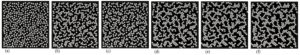 |
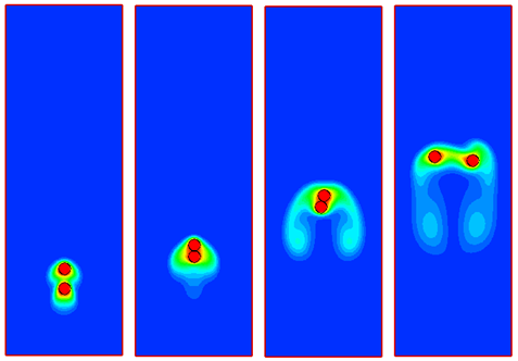
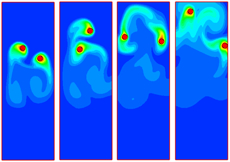
| Figure above shows the gradual formation of large agglomerated structures within the medium. The nanoparticles are polystyrene spheres with a diameter of 50 nm and a zeta potential of -100 mV. Water at standard temperature and pressure is considered as the solvent phase. The computational region is set at 1.35 um on both sides, and randomly populated with 500 nanoparticles. A small time step for DLVO force is set at 10E-11 s, and a large time step for fluid force is set at 10E-10 s. A periodic boundary condition is enforced on all four sides. The resultant DLVO force is the primary factor for agglomeration. When the attractive Van der Waals force exceeds the repulsive double layer force, the particles will tend to agglomerate. |
|
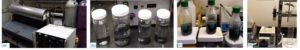
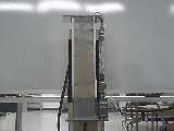
Biomass Pyrolysis in a Fluidized Bed Reactor
|
| Fast pyrolysis is one of the primary technologies to harvest energy from biomass. To facilitate biomass pyrolysis, a fluidized bed reactor is used because of its high mixing efficiency and ease of maintenance. In a fluidized bed reactor, silica sand is preheated to a high temperature (300C-600C), then nitrogen is injected through a distributor at the bottom of the bed to fluidize or lift the sand particles; at the same time, biomass particles are fed into the reactor. Violent collisions between biomass particles and sand in the high temperature and oxygenless environment cause biomass to be rapidly converted to vapors, gases and charcoal. After cooling and condensation, some of these vapors and gases turn into dark-brown bio-oil. However, particles in a biomass fluidized bed have very unique properties and characteristics due to their large density and size differences. Issues such as particle segregation and agglomeration are commonly encountered; they deteriorate the efficiency of biomass pyrolysis in the reactor.
To achieve the highest yield of bio-oil production, it is important to understand the hydrodynamics of particle-fluid flows in the bed reactor and find the optimal operating conditions. The goal of our research is to identify the optimal operating conditions and suitable configurations of biomass fluidized bed reactors for producing the highest yield of bio-oil. |
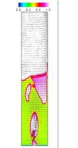 fluidization of particles in a reactor. high resolution movie fluidization of particles in a reactor. high resolution movie |
|
click here for a higher resolution video clip |
We are currently developing a numerical model for examining the particle and fluid (air) interaction in a fluidized bed and use it as a tool to investigate biomass particle fluidization in a reactor. The animation on the top right side is the result from our numerical simulation. To validate the numerical model, we have built a cold fluidized bed. The video clip on the left side is taken in our lab, which shows the fluidization of sand particles in a high velocity air flow. The experimentally measured fluid velocity, pressure drop and bed height and the visualized particle distributions will be used to compare with numerical simulation results and to improve our numerical model. |
|
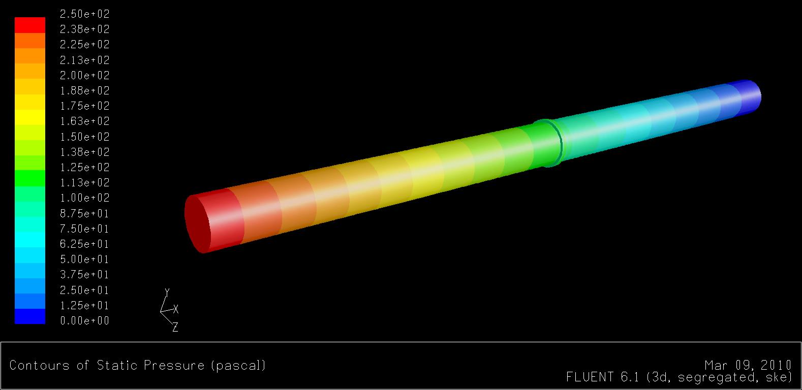
Particulate Flow and Direct Numerical Simulation
|
|
|
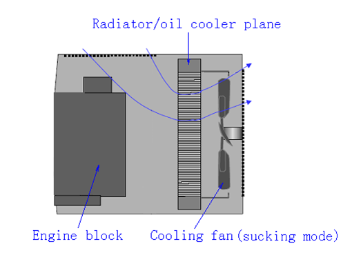
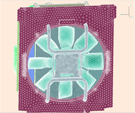
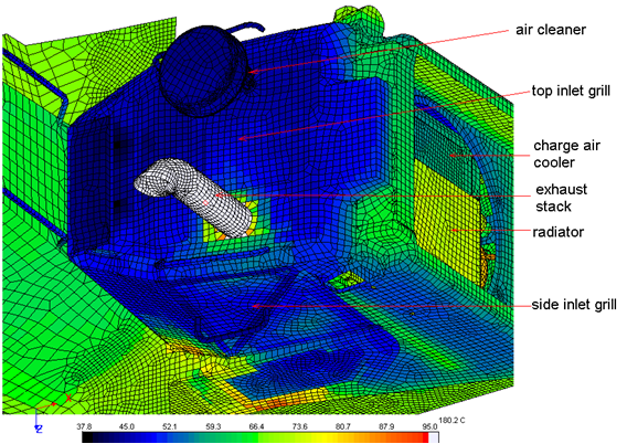
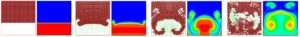
Use of CFD for Industrial Applications
|
|
|
Turbulent Modeling and Large Eddy Simulation
|
| Turbulent flow contains eddys of all kinds of scales; it is impossible to explicitly resolve the motion of small eddies, which requires a grid that is finer than the size of small eddies in numerical simulation. However, the small eddies tend to be isotropic and have a universal character, so we can model the effect of small eddies and add these effects into the equations that govern the motion of large eddies, which are the filtered (eddies less than certain size are excluded) Navier-Stokes equations, and solve the equations numerically. This technique is called Large-Eddy Simulation (LES).
LES becomes increasingly a popular computing approach for predictiong turbulent flows. One of my research interests is to develop LES model that is suitable for atmospheric boundary layer flow modeling, which has applications in wind energy related area.
| The animation on the right side shows how the concentration of mass or heat propagates from a source due to strong wind. The turbulent flow is modeled by LES method. The contour indicates the concentration of mass or heat. |
|
|